
How to Connect HC-SR501 PIR (Motion) Sensor with Arduino: Complete Guide
Welcome to our comprehensive tutorial on interfacing the HC-SR501 Passive Infrared (PIR) sensor, also known as a motion sensor, with an Arduino microcontroller. In this blog post, we’ll delve into the intricacies of connecting and understanding the functionality of the HC-SR501 PIR sensor alongside an Arduino Uno. Stay with us to explore the details and unlock the potential of motion detection in your projects.
Components Used:
Arduino Uno HC-SR501 PIR Motion Sensor Jumper Wires HC-SR501 PIR Motion Sensor Pinout:
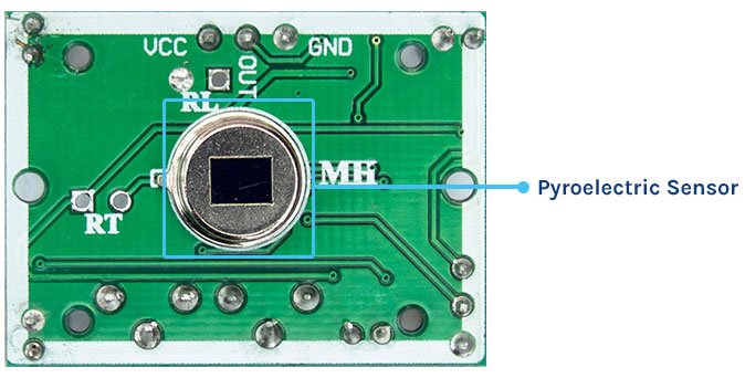
The HC-SR501 PIR sensor module comprises three essential pins: VCC, GND, and Data Output.
- VCC: Power supply pin of the module.
- Out: Data Output pin of the module, goes high upon detecting motion.
- GND: Ground pin of the module.
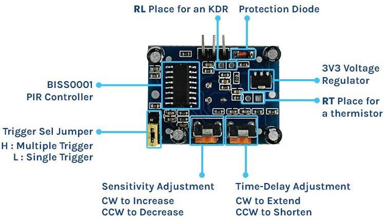
Parts of the PIR Sensor Module:
The PIR sensor module is composed of several components, each playing a crucial role in its functionality.
- Fresnel Lens: The topmost part of the sensor features a Fresnel lens, responsible for gathering parallel light rays at a focal point. This lens enhances the sensor’s range and field of view.
- Pyroelectric Sensor: Positioned at the center, the pyroelectric sensor allows infrared rays to pass through while blocking other radiation. It detects changes in radiation patterns, enabling motion detection.
- BISS0001 PIR Controller: Serving as the primary controller, the BISS0001 processes signals generated by the pyroelectric sensor, managing the sensor’s overall functionality.
- Trigger Selection Jumper: Offers two modes: Single Trigger and Repeatable Trigger, allowing flexibility in operation based on project requirements.
- Sensitivity Adjustment Potentiometer: Fine-tunes the sensor’s sensitivity, adjusting the detection range.
- Time-delay Adjustment Potentiometer: Sets the duration for which the sensor’s output remains high after detecting motion.
- RT and RL Solder Pads: Provides the option to connect additional components like thermistors and light-dependent resistors, enhancing functionality.
- 3.3V Voltage Regulator: Supplies stable power to the PIR sensor module, ensuring consistent performance.
- Protection Diode: Safeguards against reverse voltage, protecting the sensor module from damage.
How Does a PIR Sensor Work?
A PIR sensor detects IR radiation emitted by objects with a temperature above absolute zero. The HC-SR501 PIR sensor operates in several stages:
- Initialization Phase: Upon powering up, the sensor calibrates itself to ambient IR radiation conditions, minimizing false triggers.
- Motion Detection: The sensor continuously monitors its surroundings, detecting dynamic alterations in IR radiation patterns caused by moving warm objects.
- Signal Processing: Internal circuitry processes the signal output from the pyroelectric sensor, amplifying and filtering it for accurate motion detection.
- Output: The sensor typically outputs a digital signal, transitioning from low to high when motion is detected. The duration of the high state is determined by the time-delay adjustment.
Commonly Asked Questions about PIR Sensor:
- Detection Range: Typically between 5 to 15 feet (1.5 to 4.5 meters), depending on specifications.
- Reducing False Alarms: Avoid placing near heat sources, adjust sensitivity settings, and use lenses to narrow the field of view.
- Detecting through Walls: No, PIR sensors cannot detect motion through walls; they require line of sight.
Arduino PIR Motion Sensor Interfacing Circuit Diagram:
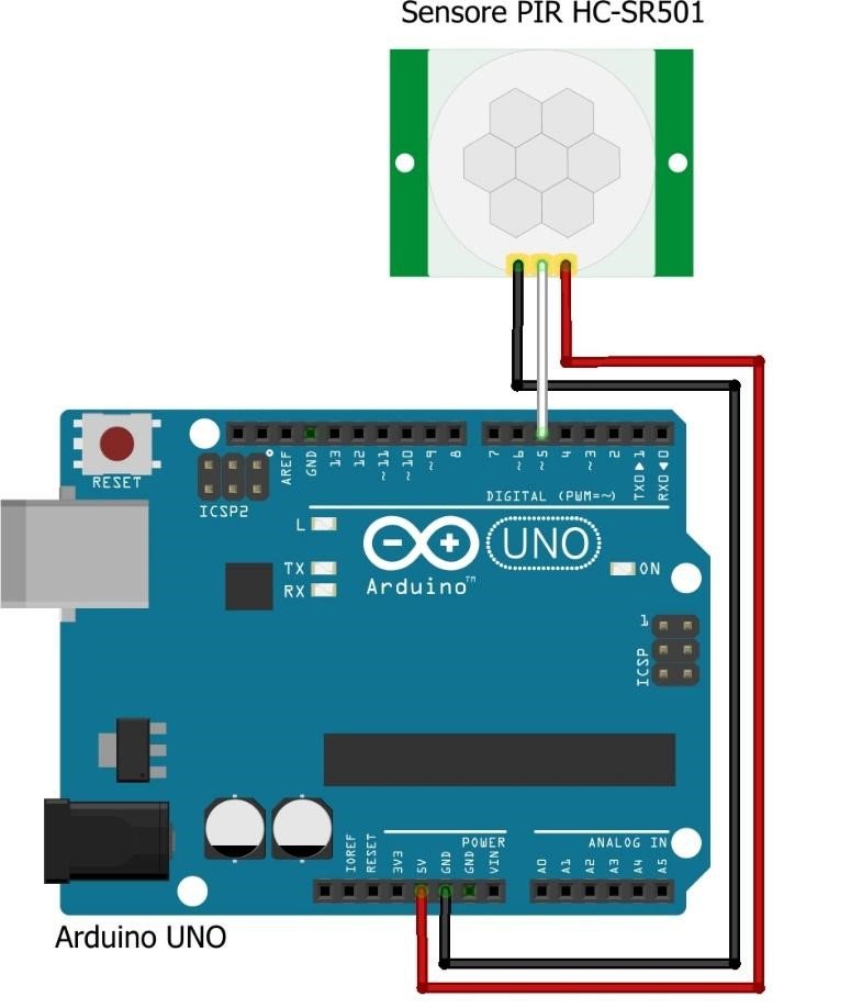
- Connect PIR sensor VCC to Arduino 5V output.
- Connect PIR sensor GND to any GND pin on the Arduino.
- Attach PIR sensor OUT to a digital input pin on the Arduino (e.g., pin 5).