
Developing an Arduino-Based Air Quality Monitoring System
Ensuring access to clean, healthy air is paramount for our overall well-being, yet concerns persist regarding air quality in various environments. In this article, we explore the creation of an Arduino-based Air Quality Monitoring System. While previously, we’ve ventured into building an IoT-based Air Pollution Monitoring System using ESP8266, for this project, we opt for simplicity, employing the widely accessible Arduino UNO board to construct a DIY air quality sensor. We’ll begin by discussing the necessary components, followed by the process of interfacing the MQ135 sensor with the Arduino board, and conclude with the coding aspect. Let’s delve straight into it.
Understanding AQI Sensor or Air Quality Index Sensor:
The Air Quality Index (AQI) serves as a standardized metric for assessing air pollution levels in specific areas at given times. It simplifies conveying information about air quality to the general public. AQI considers key air pollutants regulated globally by environmental agencies, including ground-level ozone, particulate matter (PM2.5 and PM10), carbon monoxide (CO), sulfur dioxide (SO2), and nitrogen dioxide (NO2). Each pollutant features its own scale and threshold levels, contributing to the overall AQI value. Ranging from 0 to 500, the AQI scale classifies air quality into categories indicating the level of health concern, ranging from Normal to Moderately Polluted to Toxic.
Operation of Air Quality Monitoring System:
The Air Quality Monitoring System functions by employing sensors to detect environmental parameters such as gas levels, temperature, and humidity. Analog readings from the gas sensor, linked to an Arduino’s analog pin, furnish data on air quality, which is subsequently categorized based on predefined thresholds. Simultaneously, a DHT11 sensor captures humidity and temperature data. This collected information is showcased in real-time on an OLED screen utilizing Adafruit libraries. Continuous monitoring of these parameters furnishes users with insights into air quality conditions, facilitating prompt responses to environmental changes.
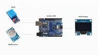
Components Required for the Project:
- Arduino board
- MQ135 gas sensor for gas detection
- DHT11 temperature and humidity sensor
- OLED display for visual output
- Breadboard and jumper wires
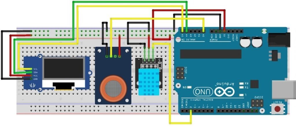
Circuit Diagram for Arduino Air Quality Monitoring System:
The circuit configuration for the air quality monitoring system entails connecting an OLED, DHT11, and MQ135 gas sensor to the Arduino Uno on a breadboard. The Arduino interfaces with the OLED via the I2C protocol utilizing the SDA and SCL pins. The MQ135 gas sensor generates analog signals routed to the Arduino’s analog input pin A0. Meanwhile, the DHT11 sensor’s digital data output pin connects to the Arduino’s D2 pin.
Conclusion:
Upon completion of the interfacing process on a breadboard, the project materializes into a functional air quality monitoring system, providing valuable insights into environmental conditions.