
A Comprehensive Guide to Interfacing Servo Motors with Arduino
Introduction:
In the realm of electronics and robotics, servo motors play a pivotal role in precisely controlling mechanical movements. This blog post serves as a comprehensive guide to interfacing a servo motor with an Arduino board. Whether you’re a novice or a seasoned enthusiast, this step-by-step tutorial will equip you with the foundational knowledge required to seamlessly integrate servo motor control into your projects. Upon mastering the basics, you can explore advanced Arduino servo motor projects, such as building a robotic arm.
Understanding Servo Motors:
Servo motors are specialized motors employed across various applications to meticulously regulate position, speed, and angular rotation in mechanical systems. These motors are engineered to deliver precise control over their output shaft, facilitating accurate angular positioning. A typical servo motor comprises a small DC motor, a gear train, a control circuit, and a feedback system. The feedback system, often comprising a potentiometer or an encoder, continually relays information about the motor’s current position to the control circuit. This feedback loop enables the control circuit to adjust the motor’s movement, ensuring it reaches and maintains the desired position.
Types of Servo Motors: Servo motors are broadly categorized into two main types:
- AC Servo Motors: Utilizing an AC power source, these motors are equipped with encoders for feedback. Renowned for their high-speed and high-torque capabilities, they find application in industrial machinery and CNC equipment.
- DC Servo Motors: Operating on a DC power source, these motors are commonly outfitted with encoders for feedback. They offer precise control and are prevalent in robotics and small-scale automation.
For this tutorial, we’ll focus on DC Servo Motors, specifically the Tower Pro SG90 Servo Motor.
Tower Pro SG90 Servo Motor:
The Tower Pro SG90 servo motor stands out as a popular micro servo motor celebrated for its compact dimensions, lightweight design, and cost-effectiveness. Widely employed in hobbyist projects, robotics, remote-controlled vehicles, and small-scale applications, the SG90 servo motor offers precise control over angular motion.
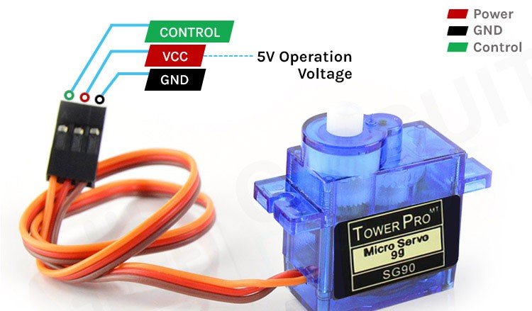
Specifications of Tower Pro SG90 Servo Motor:
- Operating Voltage: 4.8 V – 6 V
- Stall Torque: 1.6 kg-cm
- Stall Current: 650 mA
- Weight: 9g
- Operating Temperature: -30 to +60 degrees Celsius
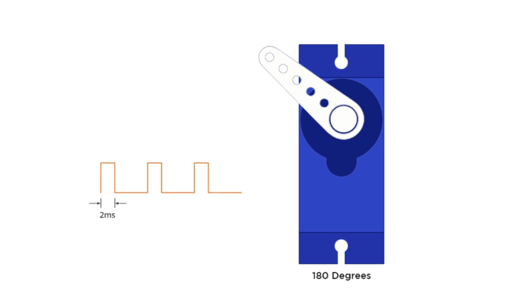
Servo Motor Working Principle:
A servo motor interprets PWM (Pulse Width Modulation) signals to determine its angle of rotation. The PWM signal, characterized by a variable duty cycle, entails a square wave where the duration of the high signal (the “on” time) corresponds to a specific angle. This signal, typically generated by a microcontroller like Arduino, is fed to the servo motor’s control input. Upon receiving the PWM signal, the motor’s control circuit translates it into a command to move to a particular angle. By comparing the measured duration of the high part of the PWM signal with the center position (usually 1.5 milliseconds), the control circuit adjusts the motor’s shaft to align with the desired angle. The servo motor continuously adjusts its position to match the incoming PWM signal, facilitating precise and repeatable angular positioning.
Controlling Servo Motors:
Aside from direct control via a microcontroller, servo motors can be managed through alternative methods:
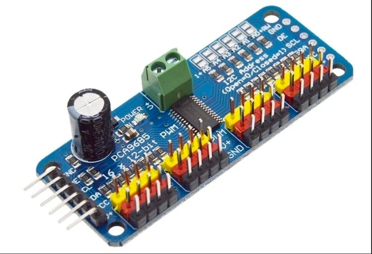
- Servo Shield: A specialized shield simplifies the control of multiple servo motors, particularly when using microcontroller platforms like Arduino.
- Servo Driver Board: Servo drivers or Arduino Servo controller boards enable the simultaneous control of multiple servo motors, making them ideal for robotics, automation, and lighting systems.
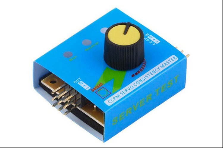
- Servo Tester: A standalone device facilitates manual testing, calibration, and control of servo motors without the need for complex programming or microcontrollers.
Common Questions about Servo Motors:
- How does a servo motor differ from a regular DC motor?
- In contrast to a standard DC motor, a servo motor is distinguished by its utilization of a closed-loop control system integrated with feedback mechanisms such as potentiometers or encoders. This configuration grants the servo motor the capability for precise position control, facilitating the halting of movement at specific angles, a feature lacking in conventional DC motors.
- Why is my servo jittering or not moving smoothly?
- In contrast to a standard DC motor, a servo motor is distinguished by its utilization of a closed-loop control system integrated with feedback mechanisms such as potentiometers or encoders. This configuration grants the servo motor the capability for precise position control, facilitating the halting of movement at specific angles, a feature lacking in conventional DC motors.
- Can I modify a servo motor for continuous rotation?
- Certain models of servo motors can indeed be altered to facilitate continuous rotation by disengaging the internal feedback mechanism and adjusting the control circuitry accordingly. This modification effectively transforms the servo motor into a geared DC motor, devoid of position control functionality.
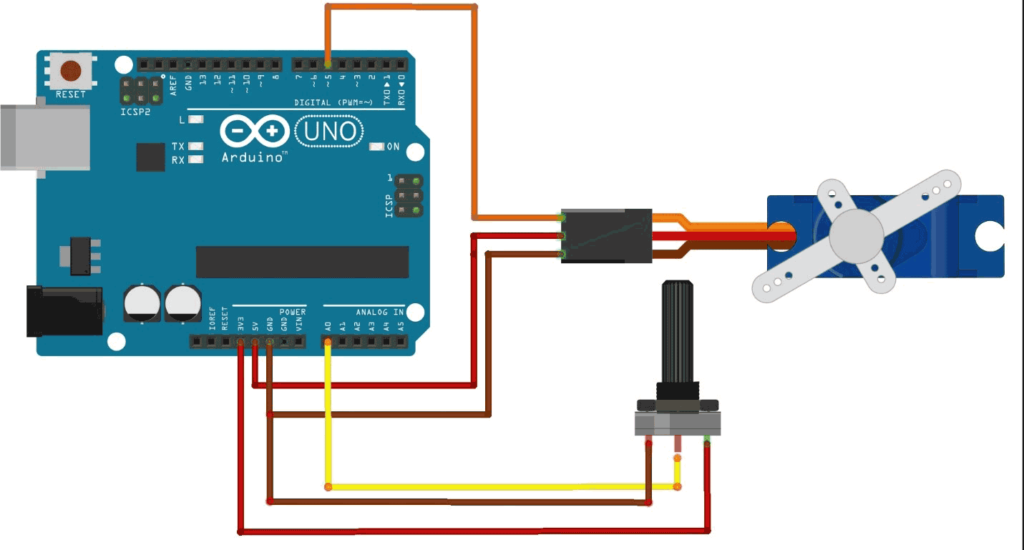
Circuit Diagram:
The circuit diagram illustrates the interface between Arduino, servo motors, and a potentiometer, showcasing a practical example of servo motor control.
Conclusion:
Armed with the knowledge gleaned from this guide, you’re equipped to embark on a journey of exploration and innovation in the realm of servo motor control with Arduino. Whether you’re crafting robotic contraptions, automating processes, or enhancing your understanding of electronics, the possibilities are limitless.