Visit our store and enjoy a flat 10% discount on all electronics components and projects. Shop now for the best deals on high-quality electronic parts and project kits! Dismiss
If you’re looking to build a home security system, set up a wildlife monitoring camera, or even trigger animated Halloween decorations when visitors approach, the HC-SR501 Passive Infrared (PIR) sensor is a great choice.
This versatile sensor detects movement from people or animals within its range, making it ideal for modern security systems, motion-activated lighting, garage door sensors, and many other applications that rely on motion detection.
Before diving deeper into its technical details, let’s explore how a PIR sensor actually works and why it’s so effective.
How does a PIR sensor work?
All objects, including the human body, emit heat in the form of infrared radiation when their temperature is above absolute zero. The higher the temperature, the more infrared radiation is emitted. While this radiation is invisible to the naked eye, the PIR sensor is designed to detect it.
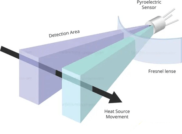
A PIR sensor is made up of two key components:-
The pyroelectric sensor, which detects infrared radiation
A special fresnel lens that focuses the infrared signals onto the pyroelectric sensor for accurate detection.
The Pyroelectric Sensor
The pyroelectric sensor contains a window with two rectangular slots, typically made from a material like coated silicon that allows infrared radiation to pass through. Behind this window are two infrared sensor electrodes—one generates a positive output and the other a negative output.
These electrodes are connected in such a way that their signals cancel each other out, as the goal is to detect changes in infrared radiation, not the ambient levels. When there’s no movement, both slots detect the same amount of infrared radiation, resulting in no output.
However, when a warm object, like a person or animal, moves through the sensor’s range, it first disrupts one half of the sensor, creating a positive differential signal. As the object continues and crosses the second half, a negative differential signal is produced. By measuring these voltage changes, the sensor can detect motion.
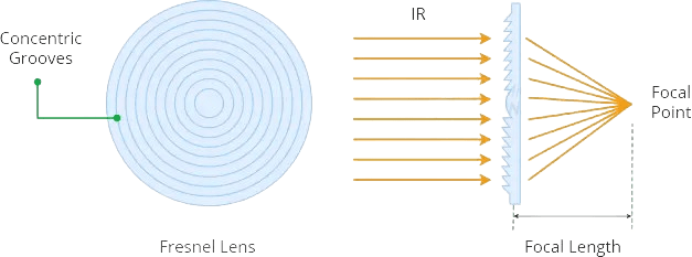
The Fresnel Lens
At first glance, the Fresnel lens might seem like it’s not doing much, but it actually plays a crucial role in extending the range and field of view of the PIR sensor. Its slim and lightweight design, along with its excellent ability to gather light, makes it possible for PIR sensors to be both compact and powerful.
The Fresnel lens is made up of a series of concentric grooves, each acting as a refracting surface that focuses parallel light rays to a point. Despite its small size, it works much like a traditional optical lens.
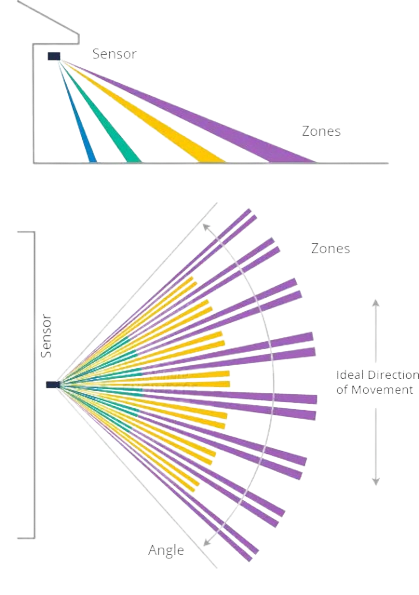
To improve the sensor’s range and field of view, the lens is divided into multiple facet sections, with each one acting as a separate Fresnel lens. These facets create overlapping detection zones, which is why the centers of the lenses appear irregular—each one focuses on a different section of the PIR sensor element.
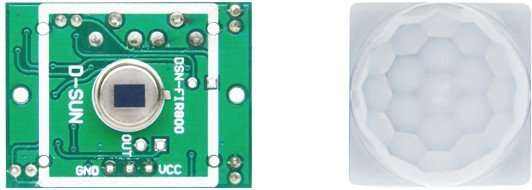
HC-SR501 PIR Sensor Hardware Overview
The HC-SR501 PIR sensor is an excellent choice for Arduino projects where you need to detect whether someone enters or exits an area. It’s affordable, energy-efficient, easy to interface with, and widely favored by hobbyists.
This sensor is simple to use and functions right out of the box. Just connect it to a power source between 5V and 12V, and ground it. The sensor’s output pin goes HIGH when motion is detected and LOW when there’s no motion.
By connecting the output to a microcontroller, you can easily trigger actions like turning lights or fans on and off.The sensor is highly efficient, drawing less than 2mA of current, and it can detect motion up to 7 meters (21 feet), with adjustable sensitivity.
BISS0001 PIR Controller
The core of the HC-SR501 module is the BISS0001, a passive infrared (PIR) controller IC. Known for its excellent noise immunity, the BISS0001 is one of the most reliable PIR controllers on the market.
This chip processes the signal received from the pyroelectric sensor and generates a digital output pulse after some basic signal conditioning.
Power
The module includes a 3.3V precision voltage regulator, allowing it to be powered by any DC voltage between 4.5 and 12 volts, with 5V being the most commonly used.
It also features a protection diode, which safeguards the module against reverse voltage and current. This means that even if you mistakenly connect the power with the wrong polarity, the module will remain unharmed.
Sensitivity Adjustment
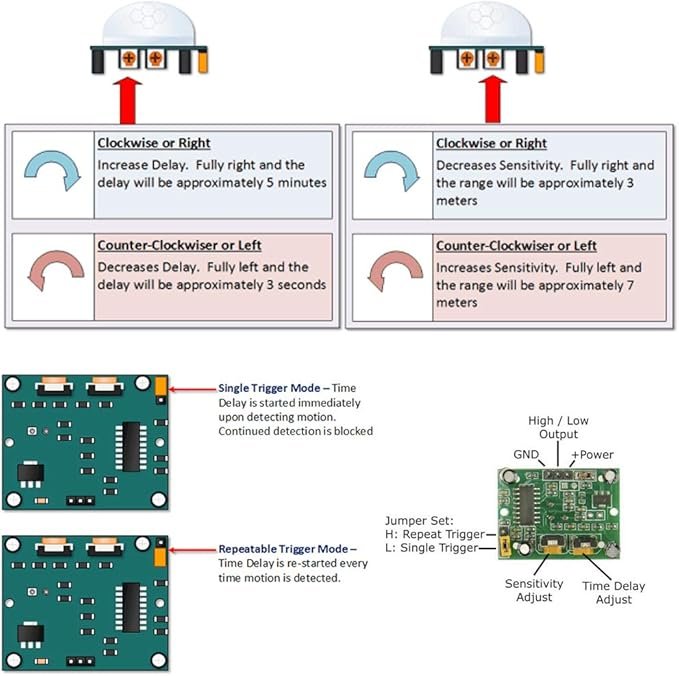
The PIR sensor is equipped with a potentiometer on the back, which allows you to adjust its sensitivity. This controls the maximum detection range, which can be set between roughly 3 to 7 meters (9 to 21 feet). Keep in mind, though, that the layout of your room may impact the actual range. Turning the potentiometer clockwise increases the sensitivity and detection range, while turning it counterclockwise decreases them.
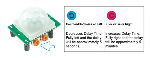
Time-Delay Adjustment
The PIR sensor also has a second potentiometer on the back to adjust the time delay. This controls how long the output stays HIGH after detecting motion, with an adjustable range from 1 second to around 3 minutes. Rotating the potentiometer clockwise increases the delay, while turning it counterclockwise reduces the delay.
Trigger Selection Jumper
There are two trigger modes that determine how the sensor will react when motion is detected.
Single Trigger Mode: The constant motion will cause a single trigger.
Multiple Trigger Mode: The constant motion will cause a series of triggers.
Single Trigger Mode: In this mode, continuous motion results in a single trigger. The output will go HIGH when motion is detected and stay HIGH for a duration set by the Time-Delay potentiometer. During this period, additional motion is ignored until the output returns to LOW. If motion continues beyond the delay, the output will briefly go HIGH again. For example, in the image below, Motion #3 is not registered.
Multiple Trigger Mode: This mode allows the sensor to trigger multiple times with continuous motion. The output goes HIGH when motion is detected and remains HIGH based on the Time-Delay potentiometer setting. Unlike single trigger mode, further motion resets the delay timer, so the output remains HIGH for each new detection until no motion is present and the output returns to LOW after the delay.
You can select between these modes using the berg jumper (or solder bridge jumper on some modules) on the board.
Optional Components – Thermistor and LDR
The HC-SR501 module includes solder pads for two optional components, typically labeled as ‘RT’ and ‘RL’. On some boards, these labels might be obscured by the Fresnel lens on the opposite side of the components.
RT – This pad is intended for a thermistor, which is a temperature-sensitive resistor. Adding a thermistor allows the HC-SR501 to function accurately in extreme temperatures, enhancing the sensor’s performance.
RL – This pad is for a Light Dependent Resistor (LDR) or photoresistor. Incorporating an LDR enables the HC-SR501 to operate in low-light conditions, making it ideal for creating motion-sensitive lighting systems.
You can solder these components directly to the module or connect them remotely using wires and connectors.
Technical Specifications
Here are the specifications:
Operating Voltage
4.5 – 20V (typically 5V)
Maximum Current Draw
< 2mA
Time Delay
~ 1 sec to 3 min
Detection Distance
3 – 7 meters (9 – 21 feet)
Detection Angle
120 degrees (typically)
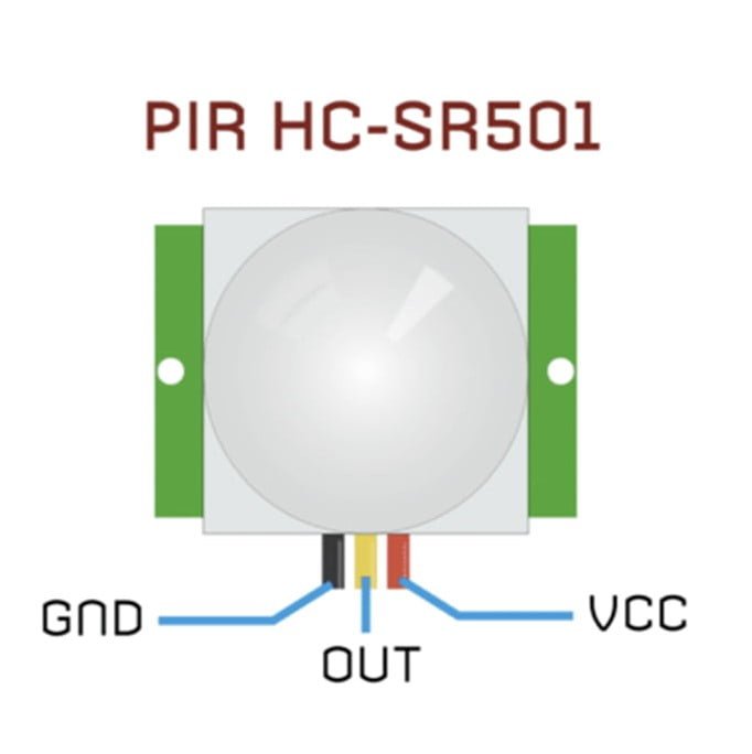
HC-SR501 PIR Sensor Pinout
The HC-SR501 has a 3-pin connector. The markings are hidden by the Fresnel lens, so refer to the following image for pinout.
VCC is the power supply for the sensor. You can connect an input voltage anywhere between 5 to 12V to this pin, although 5V is commonly used.
Output pin is the 3.3V TTL logic output. It goes HIGH when motion is detected and goes LOW when idle (no motion detected).
GND is the ground pin.
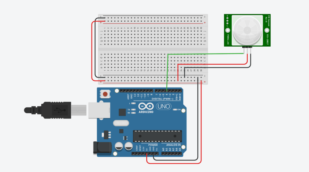
Wiring a PIR Sensor to an Arduino
To connect the PIR sensor to your Arduino, simply power the sensor with 5V and connect the ground pin to the Arduino’s ground. Since the PIR sensor provides a digital output, you just need to connect the output pin to one of the Arduino’s digital pins, such as pin #8.
For optimal operation of the HC-SR501, set the jumper to the H position (Multiple Trigger Mode). Adjust the Time-Delay potentiometer to at least 3 seconds by turning it counterclockwise to its minimum. Finally, set the sensitivity potentiometer to your preference, or if unsure, position it at the midpoint.
The following table lists the pin connections:
HC-SR501 PIR Sensor
Arduino
VCC
5V
GND
GND
OUT
4
Arduino Example Code
The code is very simple. It basically just keeps track of whether the input to pin #8 is HIGH or LOW.
int ledPin = 13;                // choose the pin for the LED
int inputPin = 4;               // choose the input pin (for PIR sensor)
int pirState = LOW;             // we start, assuming no motion detected
int val = 0;                    // variable for reading the pin status

void setup() {
  pinMode(ledPin, OUTPUT);      // declare LED as output
  pinMode(inputPin, INPUT);     // declare sensor as input

  Serial.begin(9600);
}

void loop(){
  val = digitalRead(inputPin);  // read input value

  if (val == HIGH)	// check if the input is HIGH
  {
    digitalWrite(ledPin, HIGH);  // turn LED ON

    if (pirState == LOW)
	{
      Serial.println("Motion detected!");	// print on output change
      pirState = HIGH;
    }
  }
  else
  {
    digitalWrite(ledPin, LOW); // turn LED OFF

    if (pirState == HIGH)
	{
      Serial.println("Motion ended!");	// print on output change
      pirState = LOW;
    }
  }
Things to consider before designing PIR based applications
When designing a system based on the HC-SR501 you need to keep the following delay periods in mind.
Lockout Time
When the sensor output goes LOW, it will remain LOW for about 2 seconds. During this, the motion sensing is locked-out.
For example, let’s say you have set the sensor for a time-delay of 4 seconds and set the jumper to ‘L’. So when you wave your hand in front of the sensor, the output will go HIGH for 4 seconds and then LOW for about 2 seconds. Any motion in this period is completely ignored; as you can see Motion #2 is ignored here.
Power On Delay
Like most PIR sensors, the HC-SR501 requires approximately 30 to 60 seconds after power-up to complete its initialization process. During this time, it establishes the ambient infrared signature of its surroundings, essentially calibrating itself to identify what constitutes motion.
Expect some false triggers during this calibration period, so it’s best to ignore any detections that occur during this time. Additionally, avoid excessive movement in front of the sensor while it’s calibrating, as this can disrupt the process.